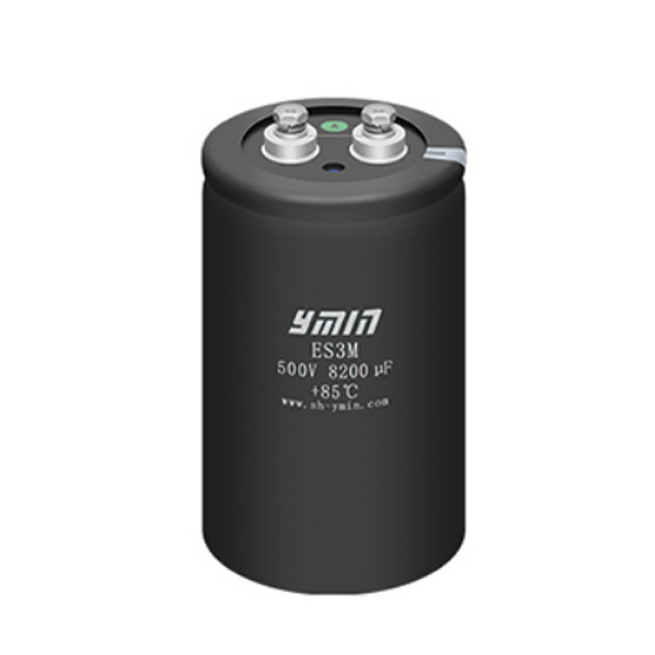
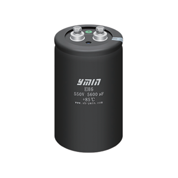
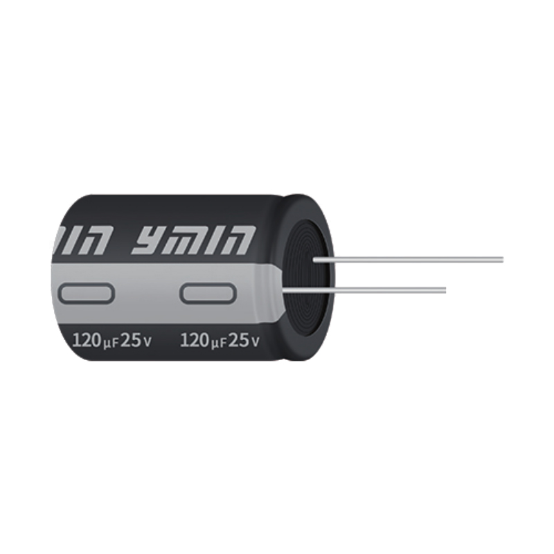
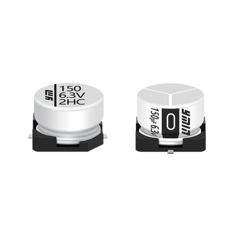
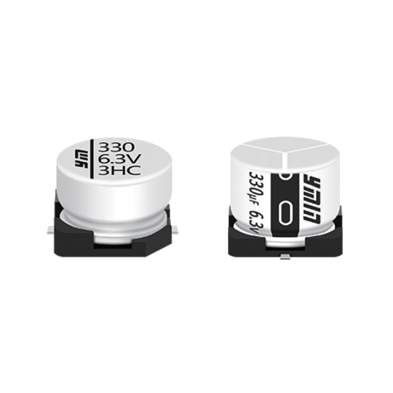
Main technical parameters
Technical Parameter
♦ 85℃ 3000 Hours
♦ Designed For Power Supply, Inverter, Medium Frequency Furnace
♦ Welding Machine, DC Welder
♦ High Ripple Current, Small Size
♦ RoHS Compliant
Specification
|
Items |
Characteristics |
|
|
Temperature Range(℃) |
-40(-25)℃~+85℃ |
|
|
Voltage Range(V) |
200~500V.DC |
|
|
Capacitance Range(uF) |
1000 〜39000uF ( 20℃ 120Hz ) |
|
|
Capacitance Tolerance |
土 20% |
|
|
Leakage Current(mA) |
≤1.5mA or 0.01 5 minutes test at 20℃ |
|
|
Maximum DF(20℃) |
0.18(20℃, 120HZ) |
|
|
Temperature Characteristics(120Hz) |
200-450 C(-25℃)/C(+20℃)≥0.7 ; 500 C(-40℃)/C(+20℃)≥0.6 |
|
|
Insulating Resistance |
The value measured by applying DC 500V insulation resistance tester between all terminals and snap ring with insulating sleeve = 100mΩ. |
|
|
Insulating Voltage |
Apply AC 2000V between all terminals and snap ring with insulating sleeve for 1 minute and no abnormality appears. |
|
|
Endurance |
Apply rated ripple current on capacitor with voltage not more than rated voltage under 85℃ environment and apply rated voltage for 3000hours, then recover to 20℃ environment and the test results should satisfy the requirements as below. |
|
|
Capacitance change rate (△C ) |
≤initial value 土20% |
|
|
DF (tgδ) |
≤200% of initial specification value |
|
|
Leakage current(LC) |
≤initial specification value |
|
|
Shelf Life |
Capacitor kept in 85 ℃ environment fbr 1000 hours, then tested in 20℃ environment and the test result should satisfy the requirements as below. |
|
|
Capacitance change rate (△C ) |
≤initial value 土20% |
|
|
DF (tgδ) |
≤200% of initial specification value |
|
|
Leakage current(LC) |
≤initial specification value |
|
|
(Voltage pretreatment should be done before test: apply rated voltage on both ends of capacitor through a resister of about 1000Ω for 1 Hrs, then discharge electricity through 1Ω/V resister after pretreatment. Place under normal temperature fbr 24hrs after total discharging, then starts test.) |
||
Product Dimensional Drawing
Dimension(unit:mm)
|
D(mm) |
51 |
64 |
77 |
90 |
101 |
|
P(mm) |
22 |
28.3 |
32 |
32 |
41 |
|
Screw |
M5 |
M5 |
M5 |
M6 |
M8 |
|
Terminal Diameter(mm) |
13 |
13 |
13 |
17 |
17 |
|
Torque(n.m) |
2.2 |
2.2 |
2.2 |
3.5 |
7.5 |
|
Diameter(mm) |
A(mm) |
B(mm) |
a(mm) |
b(mm) |
h(mm) |
|
51 |
31.8 |
36.5 |
7 |
4.5 |
14 |
|
64 |
38.1 |
42.5 |
7 |
4.5 |
14 |
|
77 |
44.5 |
49.2 |
7 |
4.5 |
14 |
|
90 |
50.8 |
55.6 |
7 |
4.5 |
14 |
|
101 |
56.5 |
63.4 |
7 |
4.5 |
14 |
Ripple Current Correction Parameter
Frequency Correction Coefficient Of Rated Ripple Current
|
Frequency (Hz) |
50Hz |
120Hz |
300Hz |
1KHz |
≥10KHz |
|
Coefficient |
0.7 |
1 |
1.1 |
1.3 |
1.4 |
Temperature Correction Coefficient Of Rated Ripple Current
|
Temperature(℃) |
40℃ |
60℃ |
85℃ |
|
Coefficient |
1.89 |
1.67 |
1 |
Screw Terminal Capacitors: Versatile Components for Electrical Systems
Screw terminal capacitors are essential components in electrical systems, providing capacitance and energy storage capabilities in a wide range of applications. In this article, we will explore the features, applications, and advantages of screw terminal capacitors.
Features
Screw terminal capacitors, as the name suggests, are capacitors equipped with screw terminals for easy and secure electrical connections. These capacitors typically have cylindrical or rectangular shapes, with one or more pairs of terminals for connection to the circuit. The terminals are usually made of metal, providing a reliable and durable connection.
One of the key features of screw terminal capacitors is their high capacitance values, which range from microfarads to farads. This makes them suitable for applications requiring large amounts of charge storage. Additionally, screw terminal capacitors are available in various voltage ratings to accommodate different voltage levels in electrical systems.
Applications
Screw terminal capacitors find applications in a wide range of industries and electrical systems. They are commonly used in power supply units, motor control circuits, frequency converters, UPS (Uninterruptible Power Supply) systems, and industrial automation equipment.
In power supply units, screw terminal capacitors are often employed for filtering and voltage regulation purposes, helping to smooth out voltage fluctuations and improve overall system stability. In motor control circuits, these capacitors assist in starting and running induction motors by providing the necessary phase shift and reactive power compensation.
Moreover, screw terminal capacitors play a crucial role in frequency converters and UPS systems, where they help to maintain stable voltage and current levels during power fluctuations or outages. In industrial automation equipment, these capacitors contribute to the efficient operation of control systems and machinery by providing energy storage and power factor correction.
Advantages
Screw terminal capacitors offer several advantages that make them preferred choices in many applications. Their screw terminals facilitate easy and secure connections, ensuring reliable performance even in demanding environments. Additionally, their high capacitance values and voltage ratings allow for efficient energy storage and power conditioning.
Furthermore, screw terminal capacitors are designed to withstand high temperatures, vibrations, and electrical stresses, making them suitable for use in harsh industrial environments. Their robust construction and long service life contribute to the overall reliability and durability of electrical systems.
Conclusion
In conclusion, screw terminal capacitors are versatile components that play vital roles in various electrical systems and applications. With their high capacitance values, voltage ratings, and robust construction, they provide efficient energy storage, voltage regulation, and power conditioning solutions. Whether in power supply units, motor control circuits, frequency converters, or industrial automation equipment, screw terminal capacitors offer reliable performance and contribute to the smooth operation of electrical systems.
| Products Number | Operating temperature (℃) | Voltage(V.DC) | Capacitance(uF) | Diameter(mm) | Length(mm) | Leakage current (uA) | Rated ripple current [mA/r.m.s] | ESR/ Impedance [Ωmax] | Life (hrs) |
| ES3M2D472ANNCG02M5 | -25~85 | 200 | 4700 | 51 | 75 | 2909 | 7680 | 0.024 | 3000 |
| ES3M2D562ANNCG03M5 | -25~85 | 200 | 5600 | 51 | 80 | 3175 | 9120 | 0.021 | 3000 |
| ES3M2D682ANNCG06M5 | -25~85 | 200 | 6800 | 51 | 90 | 3499 | 10560 | 0.019 | 3000 |
| ES3M2D822ANNDG02M5 | -25~85 | 200 | 8200 | 64 | 75 | 3842 | 10380 | 0.016 | 3000 |
| ES3M2D822ANNCG14M5 | -25~85 | 200 | 8200 | 51 | 130 | 3842 | 11280 | 0.016 | 3000 |
| ES3M2D103ANNDG04M5 | -25~85 | 200 | 10000 | 64 | 85 | 4243 | 12480 | 0.014 | 3000 |
| ES3M2D103ANNCG18M5 | -25~85 | 200 | 10000 | 51 | 150 | 4243 | 11640 | 0.014 | 3000 |
| ES3M2D123ANNEG03M5 | -25~85 | 200 | 12000 | 77 | 80 | 4648 | 14420 | 0.013 | 3000 |
| ES3M2D123ANNDG11M5 | -25~85 | 200 | 12000 | 64 | 115 | 4648 | 14520 | 0.013 | 3000 |
| ES3M2D153ANNEG06M5 | -25~85 | 200 | 15000 | 77 | 90 | 5196 | 16990 | 0.012 | 3000 |
| ES3M2D153ANNDG12M5 | -25~85 | 200 | 15000 | 64 | 120 | 5196 | 17280 | 0.012 | 3000 |
| ES3M2D183ANNEG09M5 | -25~85 | 200 | 18000 | 77 | 105 | 5692 | 19570 | 0.011 | 3000 |
| ES3M2D183ANNDG13M5 | -25~85 | 200 | 18000 | 64 | 125 | 5692 | 19800 | 0.011 | 3000 |
| ES3M2D222ANNFG06M6 | -25~85 | 200 | 2200 | 90 | 90 | 1990 | 22660 | 0.01 | 3000 |
| ES3M2D222ANNEG12M5 | -25~85 | 200 | 2200 | 77 | 120 | 1990 | 23520 | 0.009 | 3000 |
| ES3M2D273ANNFG09M6 | -25~85 | 200 | 27000 | 90 | 105 | 6971 | 26770 | 0.008 | 3000 |
| ES3M2D273ANNEG16M5 | -25~85 | 200 | 27000 | 77 | 140 | 6971 | 25800 | 0.008 | 3000 |
| ES3M2D333ANNFG12M6 | -25~85 | 200 | 33000 | 90 | 120 | 7707 | 29860 | 0.007 | 3000 |
| ES3M2D333ANNEG2M5 | -25~85 | 200 | 33000 | 77 | 75 | 7707 | 30360 | 0.007 | 3000 |
| ES3M2D393ANNFG16M6 | -25~85 | 200 | 39000 | 90 | 140 | 8379 | 34160 | 0.006 | 3000 |
| ES3M2D393ANNEG26M5 | -25~85 | 200 | 39000 | 77 | 185 | 8379 | 34800 | 0.006 | 3000 |
| ES3M2E332ANNCG03M5 | -25~85 | 250 | 3300 | 51 | 80 | 2725 | 6840 | 0.028 | 3000 |
| ES3M2E392ANNCG03M5 | -25~85 | 250 | 3900 | 51 | 80 | 2962 | 7560 | 0.023 | 3000 |
| ES3M2E472ANNCG06M5 | -25~85 | 250 | 4700 | 51 | 90 | 3252 | 8520 | 0.022 | 3000 |
| ES3M2E562ANNDG02M5 | -25~85 | 250 | 5600 | 64 | 75 | 3550 | 9090 | 0.019 | 3000 |
| ES3M2E562ANNCG11M5 | -25~85 | 250 | 5600 | 51 | 115 | 3550 | 9360 | 0.019 | 3000 |
| ES3M2E682ANNDG04M5 | -25~85 | 250 | 6800 | 64 | 85 | 3912 | 10920 | 0.016 | 3000 |
| ES3M2E682ANNCG18M5 | -25~85 | 250 | 6800 | 51 | 150 | 3912 | 11700 | 0.015 | 3000 |
| ES3M2E822ANNEG03M5 | -25~85 | 250 | 8200 | 77 | 80 | 4295 | 11920 | 0.014 | 3000 |
| ES3M2E822ANNDG07M5 | -25~85 | 250 | 8200 | 64 | 96 | 4295 | 12000 | 0.014 | 3000 |
| ES3M2E103ANNEG06M5 | -25~85 | 250 | 10000 | 77 | 90 | 4743 | 14040 | 0.013 | 3000 |
| ES3M2E103ANNDG10M5 | -25~85 | 250 | 10000 | 64 | 110 | 4743 | 14040 | 0.013 | 3000 |
| ES3M2E123ANNEG08M5 | -25~85 | 250 | 12000 | 77 | 100 | 5196 | 15660 | 0.012 | 3000 |
| ES3M2E123ANNDG13M5 | -25~85 | 250 | 12000 | 64 | 125 | 5196 | 15480 | 0.012 | 3000 |
| ES3M2E153ANNEG11M5 | -25~85 | 250 | 15000 | 77 | 115 | 5809 | 18120 | 0.011 | 3000 |
| ES3M2E153ANNDG17M5 | -25~85 | 250 | 15000 | 64 | 145 | 5809 | 18370 | 0.011 | 3000 |
| ES3M2E183ANNFG08M6 | -25~85 | 250 | 18000 | 90 | 100 | 6364 | 22040 | 0.01 | 3000 |
| ES3M2E183ANNEG14M5 | -25~85 | 250 | 18000 | 77 | 130 | 6364 | 21240 | 0.01 | 3000 |
| ES3M2E222ANNFG11M6 | -25~85 | 250 | 2200 | 90 | 115 | 2225 | 24670 | 0.009 | 3000 |
| ES3M2E222ANNEG19M5 | -25~85 | 250 | 2200 | 77 | 155 | 2225 | 25080 | 0.009 | 3000 |
| ES3M2E273ANNFG15M6 | -25~85 | 250 | 27000 | 90 | 135 | 7794 | 26160 | 0.008 | 3000 |
| ES3M2E273ANNEG18M5 | -25~85 | 250 | 27000 | 77 | 150 | 7794 | 26400 | 0.008 | 3000 |
| ES3M2E333ANNGG21M8 | -25~85 | 250 | 33000 | 101 | 160 | 8617 | 28490 | 0.007 | 3000 |
| ES3M2E333ANNFG28M6 | -25~85 | 250 | 33000 | 90 | 200 | 8617 | 28800 | 0.007 | 3000 |
| ES3M2E393ANNGG18M8 | -25~85 | 250 | 39000 | 101 | 150 | 9367 | 35830 | 0.006 | 3000 |
| ES3M2E393ANNFG30M6 | -25~85 | 250 | 39000 | 90 | 210 | 9367 | 36000 | 0.006 | 3000 |
| ES3M2V222ANNCG02M5 | -25~85 | 350 | 2200 | 51 | 75 | 2632 | 7450 | 0.042 | 3000 |
| ES3M2V272ANNCG06M5 | -25~85 | 350 | 2700 | 51 | 90 | 2916 | 8940 | 0.036 | 3000 |
| ES3M2V332ANNDG02M5 | -25~85 | 350 | 3300 | 64 | 75 | 3224 | 9360 | 0.033 | 3000 |
| ES3M2V332ANNCG10M5 | -25~85 | 350 | 3300 | 51 | 110 | 3224 | 9900 | 0.033 | 3000 |
| ES3M2V392ANNDG02M5 | -25~85 | 350 | 3900 | 64 | 75 | 3505 | 11320 | 0.028 | 3000 |
| ES3M2V392ANNCG11M5 | -25~85 | 350 | 3900 | 51 | 115 | 3505 | 10870 | 0.029 | 3000 |
| ES3M2V472ANNEG02M5 | -25~85 | 350 | 4700 | 77 | 75 | 3848 | 13370 | 0.026 | 3000 |
| ES3M2V472ANNDG06M5 | -25~85 | 350 | 4700 | 64 | 90 | 3848 | 13460 | 0.026 | 3000 |
| ES3M2V472ANNCG14M5 | -25~85 | 350 | 4700 | 51 | 130 | 3848 | 13540 | 0.026 | 3000 |
| ES3M2V562ANNEG03M5 | -25~85 | 350 | 5600 | 77 | 80 | 4200 | 15550 | 0.023 | 3000 |
| ES3M2V562ANNDG09M5 | -25~85 | 350 | 5600 | 64 | 105 | 4200 | 15500 | 0.023 | 3000 |
| ES3M2V682ANNEG07M5 | -25~85 | 350 | 6800 | 77 | 96 | 4628 | 17340 | 0.018 | 3000 |
| ES3M2V682ANNDG12M5 | -25~85 | 350 | 6800 | 64 | 120 | 4628 | 17140 | 0.019 | 3000 |
| ES3M2V822ANNEG09M5 | -25~85 | 350 | 8200 | 77 | 105 | 5082 | 19990 | 0.016 | 3000 |
| ES3M2V822ANNDG15M5 | -25~85 | 350 | 8200 | 64 | 135 | 5082 | 19760 | 0.017 | 3000 |
| ES3M2V103ANNEG12M5 | -25~85 | 350 | 10000 | 77 | 120 | 5612 | 23870 | 0.013 | 3000 |
| ES3M2V123ANNFG10M6 | -25~85 | 350 | 12000 | 90 | 110 | 6148 | 24580 | 0.012 | 3000 |
| ES3M2V123ANNEG16M5 | -25~85 | 350 | 12000 | 77 | 140 | 6148 | 25330 | 0.011 | 3000 |
| ES3M2G222ANNCG06M5 | -25~85 | 400 | 2200 | 51 | 90 | 2814 | 7450 | 0.038 | 3000 |
| ES3M2G272ANNDG02M5 | -25~85 | 400 | 2700 | 64 | 75 | 3118 | 8560 | 0.034 | 3000 |
| ES3M2G272ANNCG08M5 | -25~85 | 400 | 2700 | 51 | 100 | 3118 | 8940 | 0.033 | 3000 |
| ES3M2G332ANNDG04M5 | -25~85 | 400 | 3300 | 64 | 85 | 3447 | 10400 | 0.032 | 3000 |
| ES3M2G332ANNCG11M5 | -25~85 | 400 | 3300 | 51 | 115 | 3447 | 11040 | 0.03 | 3000 |
| ES3M2G392ANNDG07M5 | -25~85 | 400 | 3900 | 64 | 96 | 3747 | 12240 | 0.027 | 3000 |
| ES3M2G392ANNCG14M5 | -25~85 | 400 | 3900 | 51 | 130 | 3747 | 12970 | 0.026 | 3000 |
| ES3M2G472ANNEG03M5 | -25~85 | 400 | 4700 | 77 | 80 | 4113 | 14440 | 0.023 | 3000 |
| ES3M2G472ANNDG09M5 | -25~85 | 400 | 4700 | 64 | 105 | 4113 | 14180 | 0.024 | 3000 |
| ES3M2G562ANNEG06M5 | -25~85 | 400 | 5600 | 77 | 90 | 4490 | 16330 | 0.021 | 3000 |
| ES3M2G562ANNDG13M5 | -25~85 | 400 | 5600 | 64 | 125 | 4490 | 16830 | 0.02 | 3000 |
| ES3M2G682ANNEG09M5 | -25~85 | 400 | 6800 | 77 | 105 | 4948 | 17340 | 0.016 | 3000 |
| ES3M2G682ANNDG16M5 | -25~85 | 400 | 6800 | 64 | 140 | 4948 | 17840 | 0.016 | 3000 |
| ES3M2G822ANNEG12M5 | -25~85 | 400 | 8200 | 77 | 120 | 5433 | 21620 | 0.014 | 3000 |
| ES3M2G103ANNFG09M6 | -25~85 | 400 | 10000 | 90 | 105 | 6000 | 21550 | 0.012 | 3000 |
| ES3M2G103ANNEG16M5 | -25~85 | 400 | 10000 | 77 | 140 | 6000 | 22440 | 0.012 | 3000 |
| ES3M2G123ANNFG13M6 | -25~85 | 400 | 12000 | 90 | 125 | 6573 | 26620 | 0.011 | 3000 |
| ES3M2G123ANNEG21M5 | -25~85 | 400 | 12000 | 77 | 160 | 6573 | 26520 | 0.011 | 3000 |
