Main technical parameters
| Item | characteristic | ||||||||||
| Operating temperature range | ≤120V -55~+105℃ ; 160-250V -40~+105℃ | ||||||||||
| Nominal voltage range | 10~250V | ||||||||||
| Capacity tolerance | ±20% (25±2℃ 120Hz) | ||||||||||
| LC(uA) | 10-120WV |≤ 0.01 CV or 3uA whichever is greater C: nominal capacity (uF) V: rated voltage (V) 2 minutes reading | ||||||||||
| 160-250WV|≤0.02CVor10uA C: nominal capacity (uF) V: rated voltage (V) 2 minutes reading | |||||||||||
| Loss tangent (25±2℃ 120Hz) | Rated voltage (V) | 10 | 16 | 25 | 35 | 50 | 63 | 80 | 100 | ||
| tg δ | 0.19 | 0.16 | 0.14 | 0.12 | 0.1 | 0.09 | 0.09 | 0.09 | |||
| Rated voltage (V) | 120 | 160 | 200 | 250 | |||||||
| tg δ | 0.09 | 0.09 | 0.08 | 0.08 | |||||||
| For nominal capacity exceeding 1000uF, the loss tangent value increases by 0.02 for every 1000uF increase. | |||||||||||
| Temperature characteristics (120Hz) | Rated voltage (V) | 10 | 16 | 25 | 35 | 50 | 63 | 80 | 100 | ||
| Impedance ratio Z (-40℃)/Z (20℃) | 6 | 4 | 3 | 3 | 3 | 3 | 3 | 3 | |||
| Rated voltage (V) | 120 | 160 | 200 | 250 | |||||||
| Impedance ratio Z (-40℃)/Z (20℃) | 5 | 5 | 5 | 5 | |||||||
| Durability | In a 105℃ oven, apply the rated voltage with rated ripple current for a specified time, then place at room temperature for 16 hours and test. Test temperature: 25±2℃. The performance of the capacitor should meet the following requirements | ||||||||||
| Capacity change rate | Within 20% of the initial value | ||||||||||
| Loss tangent value | Below 200% of the specified value | ||||||||||
| Leakage current | Below the specified value | ||||||||||
| Load life | ≥Φ8 | 10000 Hours | |||||||||
| High temperature storage | Store at 105℃ for 1000 hours, place at room temperature for 16 hours and test at 25±2℃. The performance of the capacitor should meet the following requirements | ||||||||||
| Capacity change rate | Within 20% of the initial value | ||||||||||
| Loss tangent value | Below 200% of the specified value | ||||||||||
| Leakage current | Below 200% of the specified value | ||||||||||
Dimension (unit:mm)
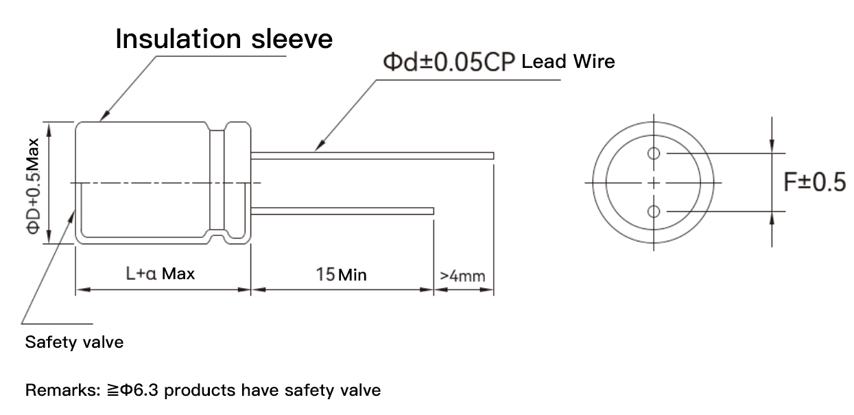
| L=9 | a=1.0 |
| L≤16 | a=1.5 |
| L>16 | a=2.0 |
| D | 5 | 6.3 | 8 | 10 | 12.5 | 14.5 | 16 | 18 |
| d | 0.5 | 0.5 | 0.6 | 0.6 | 0.7 | 0.8 | 0.8 | 0.8 |
| F | 2 | 2.5 | 3.5 | 5 | 5 | 7.5 | 7.5 | 7.5 |
Ripple current compensation coefficient
①Frequency correction factor
| Frequency (Hz) | 50 | 120 | 1K | 10K~50K | 100K |
| Correction factor | 0.4 | 0.5 | 0.8 | 0.9 | 1 |
②Temperature correction coefficient
| Temperature(℃) | 50℃ | 70℃ | 85℃ | 105℃ |
| Correction factor | 2.1 | 1.8 | 1.4 | 1 |
Standard Products List
| Series | Volt range(V) | Capacitance(μF) | Dimension D×L(mm) | Impedance (Ωmax/10×25×2℃) | Ripple Current(mA r.m.s/105×100KHz) |
| LKE | 10 | 1500 | 10×16 | 0.0308 | 1850 |
| LKE | 10 | 1800 | 10×20 | 0.0280 | 1960 |
| LKE | 10 | 2200 | 10×25 | 0.0198 | 2250 |
| LKE | 10 | 2200 | 13×16 | 0.076 | 1500 |
| LKE | 10 | 3300 | 13×20 | 0.200 | 1780 |
| LKE | 10 | 4700 | 13×25 | 0.0143 | 3450 |
| LKE | 10 | 4700 | 14.5×16 | 0.0165 | 3450 |
| LKE | 10 | 6800 | 14.5×20 | 0.018 | 2780 |
| LKE | 10 | 8200 | 14.5×25 | 0.016 | 3160 |
| LKE | 16 | 1000 | 10×16 | 0.170 | 1000 |
| LKE | 16 | 1200 | 10×20 | 0.0280 | 1960 |
| LKE | 16 | 1500 | 10×25 | 0.0280 | 2250 |
| LKE | 16 | 1500 | 13×16 | 0.0350 | 2330 |
| LKE | 16 | 2200 | 13×20 | 0.104 | 1500 |
| LKE | 16 | 3300 | 13×25 | 0.081 | 2400 |
| LKE | 16 | 3900 | 14.5×16 | 0.0165 | 3250 |
| LKE | 16 | 4700 | 14.5×20 | 0.255 | 3110 |
| LKE | 16 | 6800 | 14.5×25 | 0.246 | 3270 |
| LKE | 25 | 680 | 10×16 | 0.0308 | 1850 |
| LKE | 25 | 1000 | 10×20 | 0.140 | 1155 |
| LKE | 25 | 1000 | 13×16 | 0.0350 | 2330 |
| LKE | 25 | 1500 | 10×25 | 0.0280 | 2480 |
| LKE | 25 | 1500 | 13×16 | 0.0280 | 2480 |
| LKE | 25 | 1500 | 13×20 | 0.0280 | 2480 |
| LKE | 25 | 1800 | 13×25 | 0.0165 | 2900 |
| LKE | 25 | 2200 | 13×25 | 0.0143 | 3450 |
| LKE | 25 | 2200 | 14.5×16 | 0.27 | 2620 |
| LKE | 25 | 3300 | 14.5×20 | 0.25 | 3180 |
| LKE | 25 | 4700 | 14.5×25 | 0.23 | 3350 |
| LKE | 35 | 470 | 10×16 | 0.115 | 1000 |
| LKE | 35 | 560 | 10×20 | 0.0280 | 2250 |
| LKE | 35 | 560 | 13×16 | 0.0350 | 2330 |
| LKE | 35 | 680 | 10×25 | 0.0198 | 2330 |
| LKE | 35 | 1000 | 13×20 | 0.040 | 1500 |
| LKE | 35 | 1500 | 13×25 | 0.0165 | 2900 |
| LKE | 35 | 1800 | 14.5×16 | 0.0143 | 3630 |
| LKE | 35 | 2200 | 14.5×20 | 0.016 | 3150 |
| LKE | 35 | 3300 | 14.5×25 | 0.015 | 3400 |
| LKE | 50 | 220 | 10×16 | 0.0460 | 1370 |
| LKE | 50 | 330 | 10×20 | 0.0300 | 1580 |
| LKE | 50 | 330 | 13×16 | 0.80 | 980 |
| LKE | 50 | 470 | 10×25 | 0.0310 | 1870 |
| LKE | 50 | 470 | 13×20 | 0.50 | 1050 |
| LKE | 50 | 680 | 13×25 | 0.0560 | 2410 |
| LKE | 50 | 820 | 14.5×16 | 0.058 | 2480 |
| LKE | 50 | 1200 | 14.5×20 | 0.048 | 2580 |
| LKE | 50 | 1500 | 14.5×25 | 0.03 | 2680 |
| LKE | 63 | 150 | 10×16 | 0.2 | 998 |
| LKE | 63 | 220 | 10×20 | 0.50 | 860 |
| LKE | 63 | 270 | 13×16 | 0.0804 | 1250 |
| LKE | 63 | 330 | 10×25 | 0.0760 | 1410 |
| LKE | 63 | 330 | 13×20 | 0.45 | 1050 |
| LKE | 63 | 470 | 13×25 | 0.45 | 1570 |
| LKE | 63 | 680 | 14.5×16 | 0.056 | 1620 |
| LKE | 63 | 1000 | 14.5×20 | 0.018 | 2180 |
| LKE | 63 | 1200 | 14.5×25 | 0.2 | 2420 |
| LKE | 80 | 100 | 10×16 | 1.00 | 550 |
| LKE | 80 | 150 | 13×16 | 0.14 | 975 |
| LKE | 80 | 220 | 10×20 | 1.00 | 580 |
| LKE | 80 | 220 | 13×20 | 0.45 | 890 |
| LKE | 80 | 330 | 13×25 | 0.45 | 1050 |
| LKE | 80 | 470 | 14.5×16 | 0.076 | 1460 |
| LKE | 80 | 680 | 14.5×20 | 0.063 | 1720 |
| LKE | 80 | 820 | 14.5×25 | 0.2 | 1990 |
| LKE | 100 | 100 | 10×16 | 1.00 | 560 |
| LKE | 100 | 120 | 10×20 | 0.8 | 650 |
| LKE | 100 | 150 | 13×16 | 0.50 | 700 |
| LKE | 100 | 150 | 10×25 | 0.2 | 1170 |
| LKE | 100 | 220 | 13×25 | 0.0660 | 1620 |
| LKE | 100 | 330 | 13×25 | 0.0660 | 1620 |
| LKE | 100 | 330 | 14.5×16 | 0.057 | 1500 |
| LKE | 100 | 390 | 14.5×20 | 0.0640 | 1750 |
| LKE | 100 | 470 | 14.5×25 | 0.0480 | 2210 |
| LKE | 100 | 560 | 14.5×25 | 0.0420 | 2270 |
| LKE | 160 | 47 | 10×16 | 2.65 | 650 |
| LKE | 160 | 56 | 10×20 | 2.65 | 920 |
| LKE | 160 | 68 | 13×16 | 2.27 | 1280 |
| LKE | 160 | 82 | 10×25 | 2.65 | 920 |
| LKE | 160 | 82 | 13×20 | 2.27 | 1280 |
| LKE | 160 | 120 | 13×25 | 1.43 | 1550 |
| LKE | 160 | 120 | 14.5×16 | 4.50 | 1050 |
| LKE | 160 | 180 | 14.5×20 | 4.00 | 1520 |
| LKE | 160 | 220 | 14.5×25 | 3.50 | 1880 |
| LKE | 200 | 22 | 10×16 | 3.24 | 400 |
| LKE | 200 | 33 | 10×20 | 1.65 | 340 |
| LKE | 200 | 47 | 13×20 | 1.50 | 400 |
| LKE | 200 | 68 | 13×25 | 1.25 | 1300 |
| LKE | 200 | 82 | 14.5×16 | 1.18 | 1420 |
| LKE | 200 | 100 | 14.5×20 | 1.18 | 1420 |
| LKE | 200 | 150 | 14.5×25 | 2.85 | 1720 |
| LKE | 250 | 22 | 10×16 | 3.24 | 400 |
| LKE | 250 | 33 | 10×20 | 1.65 | 340 |
| LKE | 250 | 47 | 13×16 | 1.50 | 400 |
| LKE | 250 | 56 | 13×20 | 1.40 | 500 |
| LKE | 250 | 68 | 13×20 | 1.25 | 1300 |
| LKE | 250 | 100 | 14.5×20 | 3.35 | 1200 |
| LKE | 250 | 120 | 14.5×25 | 3.05 | 1280 |
LKE Series: Redefining the Performance Benchmark for Aluminum Electrolytic Capacitors
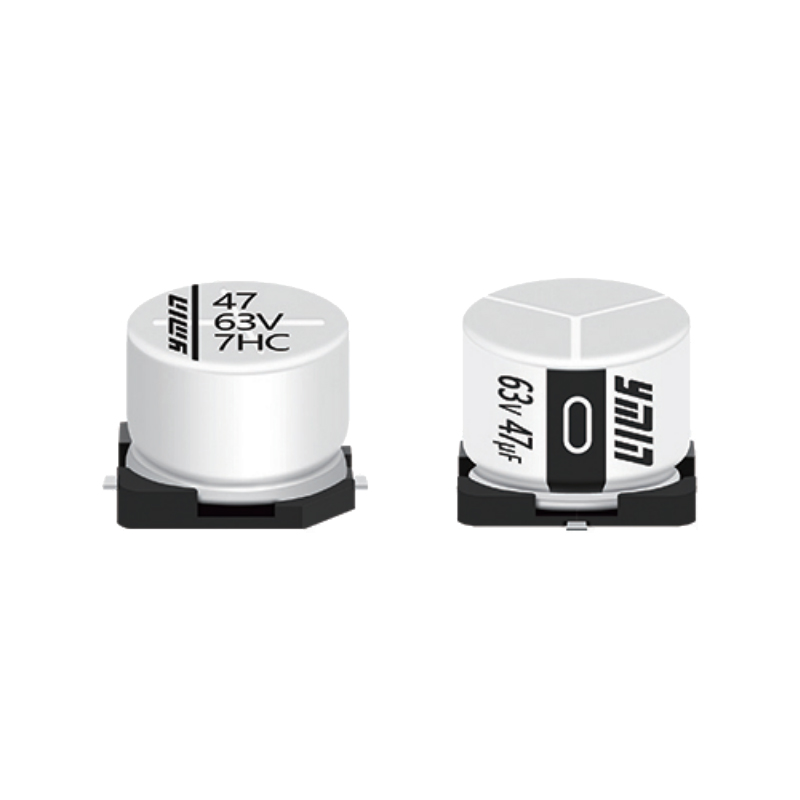
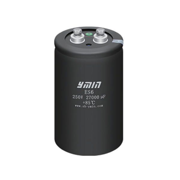
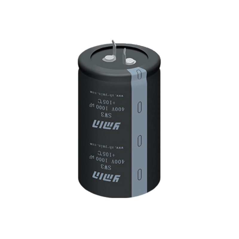
In variable-frequency drives, new energy, and high-end industrial power supplies, capacitors serve as core components for energy storage and filtering, and their reliability directly determines the lifespan of the entire system. YMIN's LKE series radial-leaded aluminum electrolytic capacitors, with a 10,000-hour lifespan at 105°C, AEC-Q200 automotive certification, and high-frequency, low-impedance characteristics, set a new standard for reliability in demanding applications.
I. Breakthrough Technical Features
1. Military-Grade Environmental Adaptability
• Ultra-Wide Operating Temperature Range:
Models below 120V support an extreme temperature range of -55°C to +105°C (160-250V models operate from -40°C to 105°C), ensuring stable operation during cold-start conditions on construction machinery in cold regions or within high-temperature motor compartments. The Z value (impedance ratio at -40°C/20°C) is controlled at 3-6 times, far exceeding the industry average of 8-10 times.
• Vibration-Reinforced Design:
This design features a radial lead mechanical reinforcement structure and has passed 5G vibration testing, making it ideal for high-frequency vibration environments such as elevator inverters and AGVs.
2. Peak Electrical Performance
Parameters Performance Indicators Industry Comparison Advantages
Ripple Current Carrying Capacity: Up to 3450mA @ 100kHz (e.g., 10V/4700μF), 40% higher than competing products.
High-Frequency Impedance Characteristics: Minimum ESR of 0.0143Ω at 10kHz, 65% reduction in high-frequency losses.
Loss Tangent (tanδ): Only 0.08 at 100Hz for the 250V specification, 15°C lower temperature rise.
Leakage Current Control: ≤0.01CV (below 120V), 50% lower self-discharge rate.
3. Lifespan and Reliability Reconstructed
• 10,000 hours @ 105°C Lifespan Verification:
In accelerated aging testing at full ripple current and rated voltage, the capacity change was ≤±20% and the loss factor increase was ≤200%, far exceeding the IEC 60384 standard.
• Self-healing safety mechanism:
An oxide film forms to self-heal during overvoltage, eliminating the risk of traditional capacitor breakdown and short circuits. This mechanism is particularly suitable for renewable energy scenarios where the power grid fluctuates frequently.
II. Vertical Industry Solutions
▶ Industrial Frequency Conversion and Servo Drives
For high-power inverters above 22kW, the LKE series addresses industry pain points with three key advantages:
1. High Frequency, Low Impedance: ESR as low as 0.03Ω at 10kHz (e.g., 50V/1500μF model), effectively suppressing IGBT switching spikes.
2. Compact Layout: 6800μF capacitance (16V specification) in a Φ14.5×25mm footprint, saving 40% of control cabinet space.
3. Vibration-Resistant Package: Capacity degradation <5% after 1500 hours of vibration testing, ensuring long-term stability for equipment such as port cranes.
Typical Configuration:
A parallel LKE 35V 2200μF (14.5×20mm) unit is used for busbar filtering in 75kW motor drives, with a ripple current capacity of up to 3150mA.
▶ New Energy Vehicle Power Systems
AEC-Q200 certified models have been used in:
• On-Board Charger (OBC): LKE100V 470μF (14.5×25mm) achieves 98.2% conversion efficiency on a 400V platform.
• PDU: 160V/180μF model exhibits less than a 4x impedance change during a -40°C cold start test.
• Commercial Vehicle Main Drive Inverter: 250V/120μF module passes 1500 temperature cycle tests (-40°C to 105°C).
▶ Key Nodes for Renewable Energy
Application Scenario Product Model Value Contribution
PV Inverter DC-Link LKE250V 120μF: Reduces DC bus ripple voltage by 47%.
Wind Turbine Pitch Control System LKE63V 1200μF: 100% low-temperature start success rate at -55°C.
Energy Storage PCS LKE100V 560μF x 6 connected in parallel: Cycle life increased to 15 years.
III. Engineering Design and Selection Guide
1. High-Frequency Scenario Selection Formula
When the switching frequency is > 20kHz, the following are preferred:
ESR-Prioritized: LKE10/16V Series (e.g., 10V/8200μF with an ESR of only 0.016Ω)
Capacitance-Prioritized: LKE35/50V Series (35V/3300μF with a capacitance density of 236μF/cm³)
2. Derating Design Model
Temperature-Frequency Composite Derating Curve:
I_{actual} = I_{rated} × K_f × K_t
Where:
• K_f (Frequency Coefficient): 1.0 at 100kHz, 0.4 at 50Hz
• K_t (Temperature Coefficient): 1.0 at 105°C, derating to 1.8x at 70°C
3. Failure Mode Prevention
• Overvoltage Protection: Operating voltage ≤ 80% of rated value (e.g., for a 250V system, select a 300V or higher model)
• Thermal Management Design: Recommended mounting spacing ≥ 2mm, combined with thermally conductive adhesive to improve heat dissipation efficiency
• Mechanical Stress Buffering: Lead bend radius > 3d (d is the lead diameter)
IV. Technological Breakthroughs Beyond Conventional Technology
1. Electrolyte Innovation
Adopting a composite carboxylic acid electrolyte achieves three major breakthroughs:
• High-temperature volatility reduced by 60% (vs. traditional ethylene glycol system)
• Low-temperature conductivity increased to 12.8mS/cm (-40°C)
• Oxidation efficiency increased by 3 times, accelerating the self-healing process
2. Structural Innovation
• Three-dimensional etched anode: 120x increase in effective surface area (200V/22μF model)
• Double sealing system: Rubber + epoxy resin seal, explosion-proof valve opening pressure reaches 1.2MPa
• Ultra-thin dielectric layer: 0.05μm nano-scale oxide film, breakdown field strength reaches 900V/μm
Why choose the LKE series?
When your system faces:
✅ Capacitor heating caused by high-frequency switching
✅ Mechanical failure caused by vibration
✅ Lifespan concerns in wide-temperature operating conditions
✅ High-density requirements within space constraints
The YMIN LKE series sets a new benchmark for industrial-grade aluminum electrolytic capacitors with its 10,000-hour lifespan, high-frequency, low-resistance characteristics, and full-temperature adaptability. It offers full voltage coverage from 10V/1500μF to 250V/120μF and supports customized electrode designs.
Contact our technical team now: ymin-sale@ymin.com for customized selection and sample support.